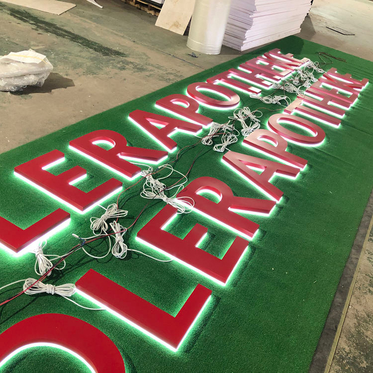
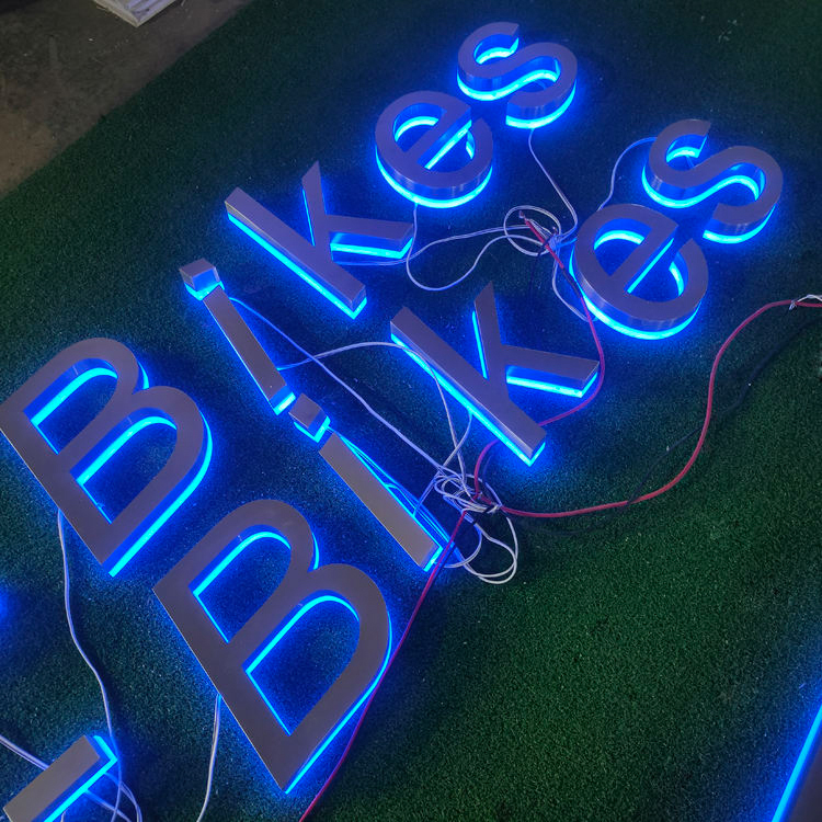
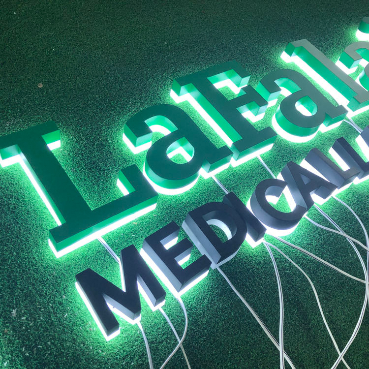
Tell us your sign type, dimensions, quantity, materials, illumination, voltage, mounting method, and delivery country. Our engineering team will review your requirements and prepare a factory quotation with recommended specifications and estimated production lead time.
Before You Leave, Get a Factory Quote
Share your drawings, dimensions, materials, quantities, illumination requirements, and delivery destination. Our signage engineering team will review your project and provide a tailored manufacturing proposal for LED letters, light boxes, pylon signs, gas station signage, or other custom sign systems.
What Drawings Are Required for Custom Sign Manufacturing?
Drawings control everything.
When a custom sign moves from an approved visual concept into metal cutting, acrylic forming, LED assembly, structural fabrication, permitting, and installation, the drawing package becomes the shared technical contract between the buyer, engineer, manufacturer, installer, and local authority.
So why do many projects still begin with nothing more than a logo and a storefront photograph?
Because the signage industry often confuses design approval with production approval. They are not the same. A rendering may show what a sign should look like, but sign fabrication drawings must explain how the sign will actually be built, powered, supported, transported, installed, serviced, and reproduced.
The minimum production package normally includes:
Approved artwork and brand references
Dimensioned sign elevations
Fabrication or shop drawings
Structural and attachment details
Electrical and LED layouts
Installation drawings or mounting templates
Material and component schedules
Permit drawings when local approval is required
Revision records and final approved-for-production drawings
Anything less leaves decisions to the factory floor.
Not every sign requires the same number of sheets. A 500 mm interior acrylic logo does not need the same documentation as a 12 m roadside pylon with LED price displays, reinforced concrete foundations, and multiple electrical circuits.
However, nearly every commercial project needs several distinct drawing types.
Drawing or document
What it must communicate
Usually reviewed by
Artwork and brand file
Logo geometry, typography, colors, spacing and proportions
Brand owner, designer, factory
General arrangement drawing
Overall size, sign type, orientation and major components
Buyer, factory, installer
Building elevation
Sign position, façade dimensions, mounting height and clearances
Owner, permit reviewer, installer
Fabrication drawing
Material thicknesses, returns, faces, frames, joints and assembly details
Factory engineering and production
Structural drawing
Steel sizes, anchors, fasteners, foundations and load path
Structural engineer, authority, installer
Electrical drawing
Voltage, wattage, circuits, power supplies, disconnects and wiring routes
Electrical engineer, electrician, factory
LED layout
Module model, quantity, spacing, power loading and cable routing
Factory, buyer, maintenance team
Installation drawing
Attachment points, drilling pattern, access method and installation sequence
Installer and site contractor
Bill of materials
Approved materials, LEDs, drivers, finishes, hardware and quantities
Procurement, quality control, buyer
Permit drawing
Planning, zoning, construction and code information required locally
Municipality or authority having jurisdiction
As-built drawing
Final installed configuration, including approved field changes
Owner, maintenance team, authority
A serious OEM signage manufacturing program should not release materials merely because the customer approved a photorealistic rendering. Dimensions, construction, illumination, voltage, mounting and finishes must first become controlled production information. That is also how Custom Signage Factory describes its OEM review and manufacturing process.
Concept Renderings Are Not Sign Fabrication Drawings
A concept rendering answers one question:
Does the customer like the appearance?
A fabrication drawing answers far harder questions:
What is the finished width, height and depth?
Is the return made from 1.0 mm aluminum, 1.5 mm aluminum or stainless steel?
Is the acrylic face 3 mm or 5 mm thick?
How is the face retained?
Where are welded joints located?
What surface finish and color reference apply?
How many LED modules are installed?
Where are the power supplies located?
How does water drain?
Which parts separate for shipping?
How will the installer reach the fasteners?
Can the power supply be replaced without removing the entire sign?
What prevents incompatible metals from creating galvanic corrosion?
Pretty pictures hide these questions.
In my view, this is one of the signage industry’s most expensive bad habits: suppliers quote from incomplete visuals, buyers compare those quotes as though the specifications were identical, and both sides discover after production begins that they priced different products.
A low quotation created from vague documents is not necessarily a competitive quotation. It may simply contain more assumptions.
The Essential Custom Sign Shop Drawings
1. Approved Artwork and Brand-Control Files
Manufacturing should begin with vector artwork rather than a compressed JPEG extracted from a website.
Preferred source files commonly include:
Adobe Illustrator AI
EPS
Editable PDF
SVG
DWG or DXF for technical geometry
STEP files when three-dimensional parts require controlled geometry
The artwork package should identify:
Exact logo version
Typeface or outlined letter shapes
Pantone, RAL, CMYK or other specified color references
Minimum clear space
Relative logo proportions
Daytime and illuminated color expectations
Approved deviations required for fabrication
Convert fonts to outlines before release. But retain a reference copy identifying the original font.
And do not redraw a global brand logo from a low-resolution photograph. That shortcut may save one hour and create years of inconsistent replacement signs.
2. Dimensioned General Arrangement Drawing
The general arrangement drawing, sometimes called a GA drawing, shows the complete sign rather than every manufacturing detail.
It should include:
Overall width, height and depth
Letter and logo dimensions
Major internal components
Front, side and rear views
Illuminated and non-illuminated areas
Sign orientation
Major mounting points
Removable access panels
Electrical entry location
Approximate finished weight
Drawing scale
Project address and sign reference number
For a set of custom LED letter signs, the GA drawing should also state whether the letters are front-lit, halo-lit, dual-lit, open-face or resin-faced. The site’s LED letter category confirms that mounting rails, voltage, materials and installation patterns may all be manufactured from approved artwork and drawings.
3. Signage Fabrication Drawings
Fabrication drawings turn the general arrangement into workshop instructions.
They normally show:
Face material and thickness
Return material and depth
Trim cap or rimless construction
Back panel construction
Internal aluminum or steel frame
Weld types and locations
Bent, folded or routed components
Drainage and ventilation points
Access doors and service panels
Gaskets, sealants and bonding methods
Removable and permanently fixed components
Fastener sizes and spacing
Surface preparation and coating system
Packing or modular split points
For an aluminum channel letter, a fabrication drawing might specify a 3 mm acrylic face, 1.0 mm aluminum return, 2.0 mm aluminum back, stainless steel fasteners, neutral-cure silicone and designated drainage openings.
For a fabricated pylon cabinet, that level of detail is nowhere near enough. The drawing may need structural steel members, cabinet framing, lifting points, ventilation, access doors, panel-retention systems and the connection between the cabinet and support column.
4. Structural and Engineering Drawings
Structural drawings define how loads travel from the sign into the building, pole, footing or supporting structure.
They may include:
Sign weight
Wind design criteria
Steel member sizes and grades
Aluminum member sizes
Weld specifications
Base plates
Anchor bolts
Chemical anchor requirements
Fastener quantity, diameter and spacing
Connection to the building frame
Concrete footing dimensions
Reinforcing steel
Soil assumptions
Allowable deflection
Engineer’s calculations and seal, where required
The hard truth is simple: a drawing that shows six bolts but does not identify what those bolts connect to is incomplete.
King County’s May 2024 sign-permit checklist provides a useful real-world benchmark. For building-mounted signs, it asks for structural material sizes and grades, sign weight, fastener size and spacing, and connection details to the building frame. For freestanding and monument signs, it additionally calls for footing size, depth and reinforcement.
That distinction matters when ordering custom pylon signs. A factory can engineer the sign cabinet and internal frame, but the foundation may still require a locally licensed engineer who knows the site’s wind speed, exposure category, frost depth, soil capacity and local building code.
5. Electrical and LED Drawings
An illuminated sign needs more than an arrow reading “connect power here.”
The electrical drawing should identify:
Input voltage and frequency
Total connected load
Estimated current
Number and rating of power supplies
Power-supply model or approved equivalent
Circuit allocation
LED module model
Module quantity
Module wattage
Series or parallel arrangement
Low-voltage cable routes
Wire size and insulation type
Grounding or bonding method
Disconnect location
Junction boxes
Penetration locations
Controller, dimmer or timer connections
Service access
Wet, damp or dry location suitability
UL Solutions identifies UL 48, UL 879, UL 879A and NFPA 70 Article 600 among the principal North American standards and requirements associated with electric signs and sign components. It also notes that UL 48 programs cover products such as channel letters, box signs, awning signs and changing-message signs.
This is why component names alone are inadequate. “Waterproof LED” tells us almost nothing. The drawing and bill of materials should record the model, electrical rating, environmental classification, quantity and approved installation method.
6. LED Module Layout
The LED layout is often combined with the electrical drawing, but complex signs deserve a separate sheet.
It should show:
Module positions
Center-to-center spacing
Number of modules per letter or cabinet
Cable direction
Power injection points
Driver loading
Maximum modules per power supply
Shadow-sensitive areas
Returns, obstructions and internal braces
Heat-sensitive components
Access to replace failed modules
A factory should not improvise module density based only on letter height. Stroke width, face material, sign depth, LED beam angle, internal surface reflectance and required luminance all affect the result.
For long-term consistency, retain the approved LED layout with the final production records. Otherwise, a replacement letter manufactured three years later may be visibly brighter than the original set.
7. Installation and Mounting Drawings
Installation drawings explain the relationship between the manufactured product and the actual site.
They should include:
Building or site elevation
Finished mounting height
Horizontal and vertical sign location
Datum points
Raceway or individual-letter mounting
Hole pattern
Anchor type and embedment
Fastener access
Cable penetrations
Power-supply location
Required clearances
Installation sequence
Lifting points
Module weights
Sealant locations
Weatherproofing treatment
Required wall reinforcement
Installer-supplied components
A full-size paper template may be useful for channel letters, but a dimensioned installation pattern is safer for international projects. Paper can stretch, shrink, tear or be printed at the wrong scale.
Add at least two reference dimensions so the installer can verify the printed template before drilling.
Drawings Required for Different Sign Types
LED Channel Letters
A production-ready channel-letter package normally includes:
Approved vector logo
Dimensioned front elevation
Side section showing letter depth
Face, return and back material specifications
Trim-cap or rimless detail
LED module layout
Power-supply loading
Raceway or individual mounting detail
Drainage details
Wiring diagram
Full-size or dimension-controlled installation pattern
For outdoor letters, the waterproofing strategy belongs on the drawing. Drainage holes, cable penetrations, power-supply placement and sealed joints should not be left as unwritten workshop knowledge.
Pylon and Monument Signs
Pylon and monument projects generally require the most extensive drawing package:
Site plan
Sign elevation
Cabinet fabrication drawings
Internal steel frame
Column and base details
Foundation plan
Reinforcement details
Anchor-bolt pattern
Wind-load calculations
Access-door details
Electrical riser or single-line diagram
LED display integration
Grounding and bonding details
Lifting and assembly plan
Installation sequence
For a pylon containing fuel-price displays, branding panels and an electronic message center, each system should have a defined interface. This is particularly relevant to complete gas station signage packages, where canopy fascia, roadside price signs and site identification may have to follow one coordinated brand standard.
Illuminated Light Boxes
Light-box drawings should define:
Cabinet dimensions
Extrusion or folded-frame profile
Face-retention method
Graphic material
Tensioning system, where applicable
Access direction
LED arrangement
Driver location
Ventilation
Drainage
Wall brackets or suspension points
Maximum unsupported spans
A menu light box mounted inside a restaurant can be fairly simple. A large exterior flex-face cabinet exposed to wind and rain is not.
Gas Station Canopy Fascia
Canopy fascia packages may require:
Existing canopy survey
Plan and elevation drawings
Panel module sizes
Subframe design
Expansion joints
Corner details
Brand-color specifications
Illuminated-logo attachment
LED strip or module layout
Driver locations
Drainage and ventilation
Interface with existing cladding
Installation sequencing around station operations
Measurement errors multiply quickly on long canopy runs. A 5 mm discrepancy at one panel joint seems minor; repeated across 30 modules, it can destroy the alignment.
Interior ADA and Wayfinding Signs
For accessible signs, shop drawings should communicate more than size and color.
They may need to define:
Raised-character height
Character spacing
Braille translation
Braille dot geometry
Finish and glare characteristics
Visual contrast
Pictograms
Mounting height
Door-side location
Clear-floor-space relationship
The U.S. Access Board states that tactile characters are generally located between 48 inches and 60 inches above the finished floor, measured using the specified character baselines. Its guidance also explains that tactile signs use raised characters with Grade 2 braille and are subject to non-glare and contrast provisions.
These are drawing requirements, not notes that should be remembered after fabrication.
Sign Permit Drawings Are Not the Same as Shop Drawings
A permit reviewer and a factory technician look for different information.
Permit drawings are intended to demonstrate compliance with planning, zoning, structural, building and electrical rules. Shop drawings are intended to manufacture and assemble the product.
There is overlap. But neither automatically replaces the other.
What Permit Drawings Commonly Show
Property and project address
Parcel or lot information
Zoning classification
Site plan
Existing signs
Proposed sign location
Building façade
Sign dimensions and area
Height above grade
Projection from the building
Setbacks
Sign copy
Illumination type
Structural attachment
Foundation details
Electrical information
Applicable code references
Licensed professional’s information
Required signatures and seals
San Francisco’s sign-permit application requires scaled drawings that locate the sign horizontally and vertically on the building and lot. The form also requests sidewalk width, sign construction, attachment method, height above ground, building projection and sign copy. It separately warns that approval of the application does not itself approve electrical wiring.
New York City makes the separation even clearer. Its Department of Buildings states that a sign project may involve multiple work permits covering sign copy, structure and electrical work, with each permit requiring its own sign-off. If the completed work changes, as-built drawings may be required before project completion.
So a supplier promising “permit drawings included” should be asked four questions:
Which jurisdiction are the drawings intended for?
Does the package include structural calculations?
Is a locally licensed engineer’s seal included?
Who is responsible for revisions after plan-review comments?
Without those answers, “permit-ready” is marketing language.
A Practical Drawing Index for Custom Sign Manufacturing
For a medium-to-large commercial signage project, I would organize the drawing package approximately as follows.
G001 — Cover Sheet and Drawing Register
Include:
Project name and address
Buyer and owner details
Manufacturer
Designer
Installer
Engineer
Sign schedule
Drawing index
General notes
Applicable standards
Revision history
Approval status
A101 — Site Plan and Building Elevations
Include:
Property boundaries
Streets and access points
Building position
Existing and proposed signs
Sign setbacks
Façade dimensions
Mounting height
Relevant architectural features
F101 — Fabrication Details
Include:
Sign sections
Material thicknesses
Frame construction
Face retention
Access panels
Drainage
Ventilation
Welding
Adhesives and sealants
Finishes
S101 — Structural Details
Include:
Member sizes
Material grades
Fasteners
Anchors
Base plates
Welds
Footings
Reinforcement
Design loads
Calculation references
E101 — Electrical and LED Layout
Include:
Input power
Connected load
Circuit schedule
Driver schedule
LED layout
Cable routes
Junction boxes
Disconnect
Grounding
Controller connections
I101 — Installation Drawing
Include:
Drilling pattern
Mounting brackets
Anchor positions
Cable penetrations
Installation sequence
Lifting method
Sealant locations
Installer-supplied items
M101 — Material and Component Schedule
Include:
Metal types and grades
Acrylic type and color
LED models
Driver models
Cable types
Fasteners
Paint system
Color codes
Adhesives
Sealants
Replacement-component references
Custom Sign Manufacturing
Revision Control: The Detail Buyers Ignore Until It Hurts
Every issued drawing should carry:
Unique drawing number
Revision number or letter
Issue date
Prepared-by name
Checked-by name
Approval status
Description of revision
Customer approval record
Useful statuses include:
For Review
For Quotation
For Engineering
For Permit
Approved for Production
As Built
Never manufacture from a drawing labeled “For Discussion.”
And never approve only selected pages without confirming that the revision applies across the entire package. A changed letter height can affect the acrylic nesting, aluminum returns, LED count, electrical loading, mounting pattern, packaging and structural weight.
One revision. Six consequences.
Common Drawing Failures That Delay Sign Production
Missing Site Dimensions
A façade photograph without a verified dimension is not a survey. Perspective distortion makes measurements unreliable, especially when the photograph is taken from street level.
Provide at least one confirmed horizontal and one vertical reference dimension.
No Wall-Construction Information
“Mount to wall” is not an attachment specification.
The wall may be reinforced concrete, structural steel, masonry, aluminum composite cladding, insulated metal panel, curtain wall, timber framing or decorative rainscreen. Each requires a different mounting approach.
Unspecified Colors
“Blue” is not a production color.
Use Pantone, RAL, paint-manufacturer codes, approved physical samples or measured color data. Also distinguish daytime face color from nighttime illuminated appearance.
No Voltage or Electrical Standard
A sign cannot be engineered correctly if the factory does not know whether the project uses 120 V/60 Hz, 230 V/50 Hz, 24 VDC or another system.
Voltage affects drivers, wiring, certification, testing and labeling.
Unapproved Component Substitutions
A drawing that specifies one power supply while the quotation assumes another creates conflict before production begins.
Every approved substitution should be documented in the bill of materials or drawing revision.
No Maintenance Access
A sealed cabinet may look clean on screen and become a maintenance nightmare on site.
Draw the access panel. Draw the fasteners. Draw the clearance needed to remove the driver.
Manufacturing Before Structural Approval
This happens more often than buyers admit.
The cabinet is fabricated, the engineer increases the steel section or anchor spacing, and suddenly the internal frame, base plate, access panel and shipping crate all need modification.
Complete structural review before releasing load-bearing components.
The Best Drawing Package for Custom Sign Manufacturing
The best drawing package is not the package with the most pages. It is the package that removes meaningful ambiguity.
Before approving production, confirm that the documents answer these questions:
Is the exact logo geometry approved?
Are all overall dimensions confirmed?
Are material types and thicknesses stated?
Are colors tied to objective references?
Is the illumination method clear?
Are LED and power-supply models recorded?
Is the operating voltage confirmed?
Is total power loading shown?
Are mounting points dimensioned?
Is the supporting wall or foundation identified?
Are anchors and fasteners specified?
Are drainage and service access shown?
Are separable shipping sections identified?
Has a licensed engineer reviewed structural work where required?
Has the installer reviewed site conditions?
Is the final revision clearly marked Approved for Production?
When those answers are documented, quotation accuracy improves, production arguments decline, inspection becomes measurable, and repeat orders become far easier to control.
FAQs
What drawings are required for custom signs?
A complete custom sign manufacturing drawing package is a coordinated set of scaled visual, fabrication, structural, electrical, mounting, and revision-controlled documents that tells the permit reviewer, engineer, factory, installer, and buyer exactly what will be built, how it will be powered, and how it will be attached.
The exact documents depend on sign type and location. Small interior signs may need only artwork, elevations and mounting details, while large exterior pylons may require site plans, structural calculations, foundations, electrical diagrams and locally sealed permit plans.
What is the difference between sign shop drawings and permit drawings?
Sign shop drawings are manufacturing documents that specify materials, dimensions, component construction, LED arrangements, fasteners, finishes and assembly methods, while permit drawings are compliance documents that show site location, zoning information, sign area, height, setbacks, structural support, electrical scope and other information required by the local authority.
Some sheets can serve both purposes, but permit approval does not automatically mean the factory has enough information to manufacture the sign accurately.
Does every sign require drawings from a structural engineer?
A structural engineer is generally required when the sign, support, attachment or foundation presents structural risk or when the local authority, building code, property owner or contract requires engineered calculations and sealed drawings, particularly for pylons, monuments, projecting signs, roof signs and large or heavy wall-mounted signs.
The engineer should be licensed in the project jurisdiction when local sealing authority is required. The sign manufacturer may provide fabrication data, but local wind, soil and building conditions must still be verified.
Can a rendering be used as a sign fabrication drawing?
A rendering is a visual approval document that communicates appearance, proportion, color and placement, but it is not normally a sufficient fabrication drawing because it does not reliably define material thicknesses, structural connections, LED spacing, wiring, fasteners, service access, drainage, tolerances or installation requirements.
The rendering should be included as a visual reference, then supported by dimensioned technical drawings and an approved bill of materials.
What file formats should be sent to a custom sign manufacturer?
The best file package combines editable vector artwork such as AI, EPS, SVG or PDF with dimensioned technical files such as DWG or DXF, plus a controlled PDF set for approval, because the editable files support accurate production while the PDF preserves the approved layout, dimensions, notes and revisions.
Provide linked images, font information, color references and three-dimensional STEP files where relevant. Do not rely on screenshots, web logos or compressed JPEG files as the only artwork source.
Who should approve sign fabrication drawings?
Sign fabrication drawings should be approved by the party controlling brand appearance, the buyer responsible for commercial scope, the engineer responsible for structural design, the electrical or compliance professional where applicable, the manufacturer responsible for production, and the installer responsible for actual site conditions and mounting feasibility.
Not every person must stamp every sheet, but responsibilities should be defined. A buyer’s visual approval should never be treated as engineering approval unless that authority has been explicitly assigned.
Send Your Drawings for a Manufacturing Review
Do not wait until production begins to discover that the mounting structure, voltage, letter depth or finish was never confirmed.
Prepare your vector artwork, dimensions, quantity, sign type, installation location, electrical requirements, reference photographs and available architectural drawings. Then submit them through the Custom Signage Factory project enquiry page for an OEM manufacturing review.
We will review the proposed construction, materials, illumination, mounting method and production feasibility before quotation and help identify the missing information required for an approved manufacturing package.
Custom Signage Factory manufactures commercial signs for sign companies, contractors, distributors, and multi-site brands. With a 20,000 m² workshop, 80+ production workers, 50+ machines, and an annual capacity of 100,000 pieces, we produce LED letters, light boxes, pylon signs, gas station signage, neon signs, and custom OEM sign systems.